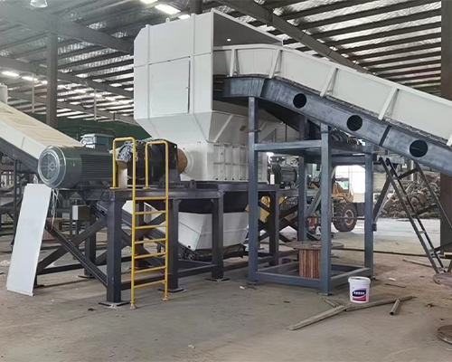
double-shaft shredder
Date:2025-01-06
View: Point
The working principle of the double-shaft shredder is as follows:
Power transmission
Usually, a dual-motor dual-reducer design is adopted. Two high-torque motors provide power. The power is transmitted to the gear reducer through transmission methods such as V-belts. The gear transmission structure inside the reducer greatly reduces the speed and proportionally increases the torque. The power after deceleration and torque increase drives the two shredder main shafts, causing the two main shafts to move and rotate in relative directions.
Material shredding
When the material enters the shredding box through the feeding system, the material is clamped by the claw structure on the knife shaft. The two shafts equipped with blades rotate relative to each other, and the blades interlock with each other. Under the action of the blades, strong shearing force, extrusion force and tearing force are applied to the material. Through the combined action of these forces, the material is torn, cut and squeezed into small pieces. For example, when processing waste tires, the two shafts rotate in opposite directions, and the blades quickly tear the tires into small pieces.
Discharging control
The discharging particle size of the double-shaft shredder can be controlled in many ways. Blades and teeth of different widths, quantities and shapes can be replaced according to different materials and discharging requirements. When the number of claws is increased, the tearing size of the material by the claws becomes smaller; when the number of claws is reduced, the particle size of the output material becomes larger. The gap between the blades on the two shafts can also be adjusted. The smaller the gap, the smaller the particle size of the shredded material.
During the entire working process, some double-shaft shredders are also equipped with hydraulic pushing devices, which can force the material to the rotor to ensure that the material enters the shredding area continuously and stably. In addition, the equipment is usually equipped with mechanical and electrical overload protection devices. When the processed material is too large or too much, the forward and reverse operation and shutdown functions can be used to protect the machine body.
| Model | 600 | 800 | 1000 | 1200 | 1400 | 1600 | 1800 |
| Motor(kw) | 11*2 | 18.5*2 | 35*2 | 45*2 | 55*2 | 75*2 | 110*2 |
Reducer | P6-P7 | P7-P8 | P8-P10 | P10-P12 | P11-P13 | P12-P16 | P14-P16 |
| Siemens or other motors, planetary reducers or other reducers can be customized according to customer requirements | |||||||
| Rotation Speed | 8-20rmp | 8-20rmp | 8-15rmp | 8-15rmp | 8-15rmp | 8-12rmp | 8-12rmp |
| Blades Diameter | 220-320 | 260-320 | 260-400 | 400-500 | 400-500 | 500 | 500 |
| Blades material | The material of the blades (55sicr, 5crsi, 9crsi, skd11, m6v, h13) can be customizedaccording to the customer's actual usage | ||||||
| Feeding Size | 1200*900mm | 1400*1000mm | 1600*1200mm | 1800*1300mm | 2000*1300mm | 2200*1700mm | 2400*2000mm |
| The size and appearance of the feeding hopper can be customized according to thecustomer's feeding situation | |||||||
| Weight(kg) | 1800 | 2500 | 3700 | 5500 | 7500 | 9500 | 13000 |

Zhongcheng Machinery Will Be There Whenever Wherever Whatever You Need
You Are Welcome to : phone call, Message, Wechat, Email& Seaching us, etc.
Email:
sales@zchmachinery.com
Whatsapp/Phone:
+8618738194110
hot Products
-
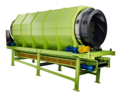 Trommel screenTrommel screen, also known as drum screens, are widely used in various industries for sorting and separating materials.Get Quote
 -
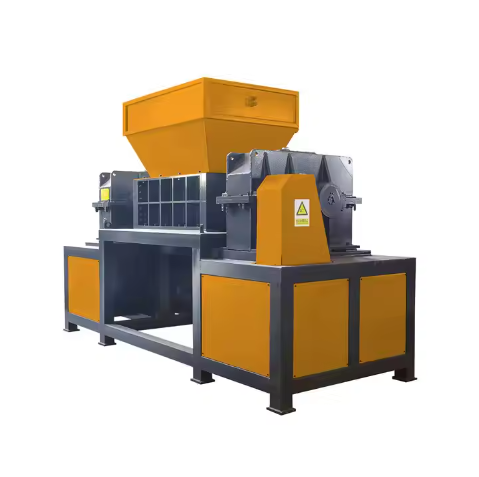 Crop straw double shaft shreddApplications:Biomass Energy Production: Shredded straw can be used as a feedstock for bioenergy plants to produce electricity or heat.Livestock Feed: Reduced-si...Get Quote
 -
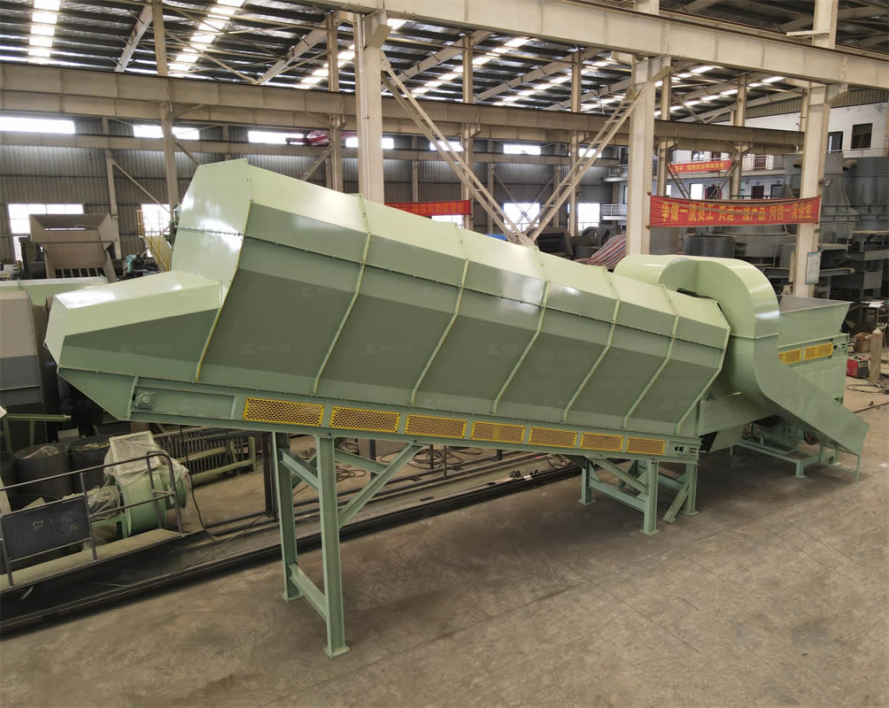 Zhongcheng Air Drum SeparatorAir drum separators effectively separate lightweight materials (e.g., plastics, paper) from heavier materials (e.g., metals, glass). This high efficiency is cru...Get Quote
relate news
-
2024-08-22Medical waste shredderWorking Principle:Feeding Mechanism: Medical waste is fed into the shredder through a hopper or chute. The feeding mechanism ensures that the waste is introduce...
-
2025-03-03Mini Copper Wire GranulatorThe copper wire granulator machine is a device specially used to process waste wires and cables. Its main function is to separate the copper and plastic in the ...
-
2024-08-05Hot-sell Coconut Shredderworking principleCoconut shell shredder usually uses the force generated by cone and spiral to evenly squeeze the coconut meat in the grinding chamber between t...
-
2024-05-29Landfill stale garbage screening projectAfter communicating with our domestic customers in Shandong Province, we learned that he needed to dispose of the garbage in the landfill through excavation, sc...
-
2024-08-12Wood Pallet ShredderConsiderations When Choosing a Wood Pallet Shredder:Material Type: Different wood types may require specific configurations or materials of construction.Output ...